
SFP vs QSFP: Key Differences Explained
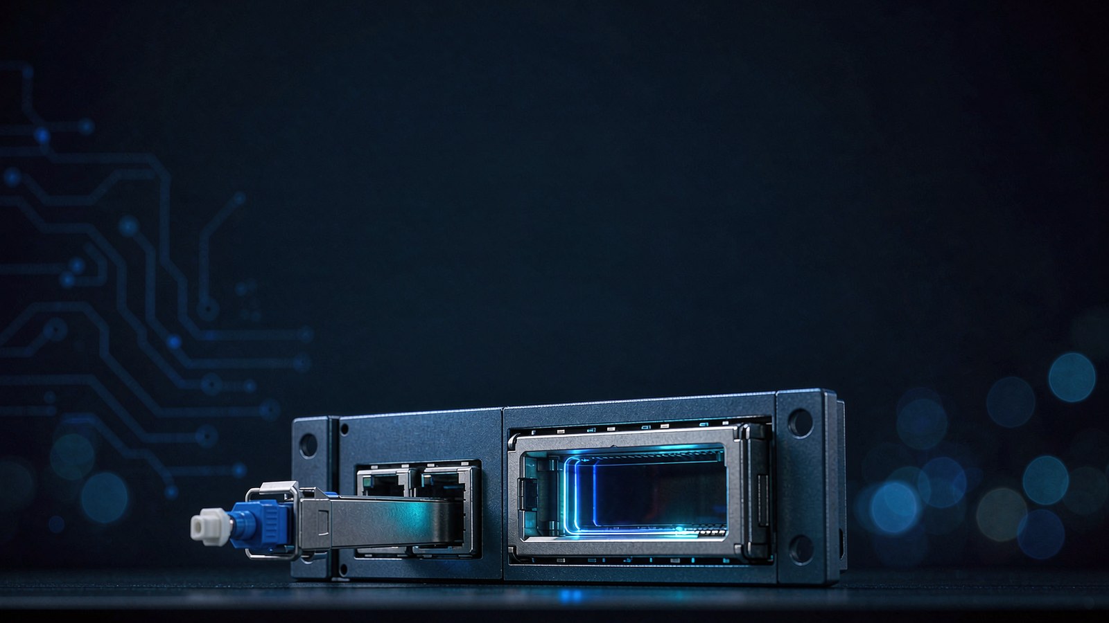
The short version. SFP and QSFP name the socket, not the speed. A single SFP cage hands one serial lane to the switch ASIC; a QSFP cage hands over four, and QSFP-DD eight. Everything a buyer argues about later — how many fibers a link consumes, whether one port can be carved into four, how many watts land on the faceplate, whether the host will even light the port — follows from that one number.
That is why the useful comparison is not "10G against 100G." Line cards blur that distinction. A 100G QSFP28 port can be instructed to behave like four 25G ports. A 10G SFP+ port cannot be instructed to behave like anything but itself. The cage sets the options; the module only picks one.
This guide works through the difference in the order a network team meets it: the hardware, the numbers, what the fourth lane costs you, where single-lane optics still win, and the rules that decide whether a link comes up at all.
The cage is the product, and the lane count is the specification
SFP began as the replacement for the bulky GBIC, and its mechanical envelope was frozen early: roughly 13.4 mm wide, 8.5 mm tall, 56.5 mm deep, with a 20-pin card-edge connector and a single 3.3 V rail. SFP+ did not enlarge that shell. It raised the electrical ceiling to 10.3125 Gbps on the same footprint, which is precisely why a 10G optic can physically enter a 1G cage — and why the outcome then depends on whether the ASIC can clock that rate. The baseline documents are INF-8074 for the original envelope, SFF-8431 for the 10G electrical spec, and SFF-8472 for the diagnostic map.
QSFP takes the same design language and widens it to four lanes: about 18.35 mm wide, 8.5 mm tall, 72.4 mm deep, 38 pins, specified through SFF-8436 for the 40G generation and SFF-8665 for the 100G one. The rate ladder is simply lane count multiplied by lane speed — 4 × 1G in the original QSFP, 4 × 10G for QSFP+, 4 × 25G for QSFP28, 4 × 50G PAM4 for QSFP56. QSFP-DD adds a second row of contacts and doubles to eight lanes, which is how 400G fits inside a cage that still resembles its ancestor.
Five millimetres of extra width sounds trivial until you count cages across a 1U faceplate. Narrow single-lane cages fit 48 across; the wider four-lane ones fit 32 to 36. You trade port count for bandwidth per port, and that trade is the whole argument. For a fuller treatment of how these envelopes evolved, see our note on data center form factor evolution.
SFP vs QSFP at a glance
| Parameter | SFP family (SFP / SFP+ / SFP28 / SFP56) | QSFP family (QSFP+ / QSFP28 / QSFP56 / QSFP-DD) |
|---|---|---|
| Serial lanes per module | 1 | 4 (8 on QSFP-DD) |
| Lane rate in common use | 1G, 10G, 25G, 50G PAM4 | 10G, 25G, 50G PAM4 |
| Aggregate rate ladder | 155M 1G 10G 25G 50G | 40G 100G 200G 400G |
| Edge connector | 20-pin | 38-pin (76-pin on DD) |
| Shell width × depth | ≈13.4 × 56.5 mm | ≈18.35 × 72.4 mm |
| Optical interface | Duplex LC, or RJ45 on copper parts | MPO-12 for parallel optics, duplex LC for WDM variants |
| Management map | SFF-8472 (A0h / A2h pages) | SFF-8636; CMIS on QSFP-DD and later |
| Typical module power | under 1 W (1G), 1–1.5 W (10G long reach) | 3.5–6 W at 100G, up to 12 W with DSP at 400G |
| Port breakout | Not possible | 40G 4×10G, 100G 4×25G, 400G 4×100G or 8×50G |
| Cages across 1U at 48-port density | 48 | 32–36 |
| Usual layer | Access, edge, long-haul, PON, industrial | Aggregation, spine, leaf uplinks, AI east-west |
What the fourth lane actually buys — and what it charges
The commercial case for QSFP is not raw bandwidth. It is that one physical port can be divided. A 100G QSFP28 port configured as 4 × 25G serves four servers from a single ASIC port; a 40G QSFP+ port split into 4 × 10G does the same for an older server pool. On a 32-port 100G leaf switch, breaking out 24 of those ports yields 96 server-facing 25G links plus eight ports still running at 100G for uplinks. That arithmetic is why leaf-spine designs converged on the four-lane cage.
There are three physical ways to build the fan-out, and they are not interchangeable:
- Breakout DAC — one QSFP shell on the switch end, four SFP shells on the server end, copper throughout. Cheapest and lowest power, but confined to a few metres inside the rack.
- Breakout AOC — the same split in factory-terminated fiber, comfortable across a row, still fixed-length.
- Parallel optic plus harness — an SR4 or PSM4 module in the QSFP port and an MPO-to-4×LC fan-out to four discrete single-lane modules. This is the option that survives structured cabling, because each leg terminates in a normal patch panel port.
The trap is software, not optics. A port that has been physically fanned out will keep behaving as one 100G interface until the operating system is told otherwise; the four sub-interfaces do not appear on their own, and the exact command differs by network OS. The second trap is FEC. On a 25G breakout, the server-side optic and the QSFP sub-port must agree on Reed-Solomon framing, and a mismatch produces the classic symptom of sub-interfaces that exist, report light, and never pass traffic.
Breakout also has a blast radius. One contaminated MPO endface, or one bent leg of a fan-out harness, can take out four server links at once rather than one. On access ports that is an acceptable trade; on a link that must deliver a full 100G to a single host, breakout is simply the wrong tool.
Where SFP+ still wins the argument
Four lanes are not automatically better. There is a long list of jobs where a single-lane cage is the correct answer, and most of them are outside the hyperscale core.
Distance. A 10G SFP+ ZR module reaches 80 km over one duplex pair on 1550 nm — our BLS558-77BL does exactly that, with ER parts for 40 km and LR for 10 km on the same shell. Comparable QSFP reaches stop far shorter: 100G ER4 tops out around 40 km and costs several times more per port. When the span is a town apart, one lane and one fiber pair is the economical answer.
Fiber scarcity. Bidirectional 10G optics transmit on one wavelength and receive on another, so a single strand carries the whole link. Our BLB series covers 20 km, 40 km and 60 km in that form. On a duct that is already full, halving strand count beats doubling lane count.
Wavelength multiplexing. CWDM and DWDM SFP+ parts let you put many 10G channels on one pair through passive optics — the BLC and BLD families run 20, 40 and 80 km across the band. There is no comparably cheap four-lane equivalent, because the multiplexing happens outside the module.
Copper drops. A 1000BASE-T SFP lets a fiber port serve an RJ45 run, which is how access switches absorb legacy cabling without a media converter.
Density at 25G. SFP28 doubles down on the narrow cage: 25.78 Gbps on a single lane means a 48-port 1U access switch, not a 24-port one. Our BLM11C, BLM333 and BLM336 cover 100 m multimode through 40 km single mode in that form.
Spares. A mixed estate stocked with single-lane optics keeps one spare per reach class. A four-lane estate keeps a spare per speed and per coding, and the sparing budget grows faster than the port count.
The rules that decide whether the port comes up
Specification tables describe what should work. Six rules describe what actually does.
- The speed ceiling lives in the host, not the module. A QSFP28 port will normally accept a 40G QSFP+ optic and run it at 40G. The reverse fails — a QSFP+ port cannot clock a 100G module. The same asymmetry governs SFP: dual-rate SFP+ ports step down to 1G, but a 1G-only cage cannot drive a 10G part.
- Rate steps down, form factor does not. An SFP optic cannot enter a QSFP cage without a purpose-built adapter, and the adapter only works where the network OS supports it. Physical fit and logical support are separate approvals.
- The identity page is part of the product. Two modules with identical optics can carry different EEPROM content, and platforms that check vendor identity will refuse the wrong one. This is the mechanics behind EEPROM coding and compatibility.
- Management maps changed generation. SFP speaks SFF-8472, QSFP+ and QSFP28 speak SFF-8636, and QSFP-DD and newer speak CMIS. A host expecting CMIS can label a perfectly healthy legacy-map module "unsupported."
- FEC is negotiable only if both ends agree. Above 50G per lane, Reed-Solomon KP4 framing is mandatory rather than optional, and any break in the chain — module, cable, far-end host — shows up as corrected errors climbing instead of a clean link.
- Thermal budget is a port-count decision. A 400G DSP-based module can draw twelve times what a 1G SFP draws. Filling every cage on a line card is not the same as filling every cage within its thermal design.
| Module in hand | Port on the switch | Result |
|---|---|---|
| 1G SFP | SFP+ dual-rate port | Runs at 1G |
| 10G SFP+ | 1G-only SFP port | No link — host cannot clock it |
| 40G QSFP+ | QSFP28 port | Runs at 40G, usually accepted |
| 100G QSFP28 | QSFP+ port | No link — exceeds host capability |
| 25G SFP28 | QSFP28 port set to 4×25G | Works only through a breakout assembly and matching FEC |
| Any SFP | QSFP port | Fails without an adapter, and only where the OS allows it |
Choosing in the right order
Start with the endpoint, not the module. What rate does the device actually need, and over what distance? Then ask which budget binds: if fiber strands or trenching cost dominate, single-lane and WDM win; if rack units and ASIC ports dominate, four-lane and breakout win. Only then pick the part — and confirm the port profile and coding before the purchase order, not after the modules arrive.
That ordering explains why the two form factors coexist rather than compete. A 10G SFP+ LR at the access layer and a 100G QSFP28 uplink on the same switch are not a compromise; they are the same decision made twice, once per constraint. Our SFP+, QSFP+ and QSFP28 pages list the reach classes and part numbers for each side of that split, and the 25G-to-100G leaf-spine note works through the port arithmetic in more detail.
FAQ
Can an SFP+ module be used in a QSFP port?
Not directly. The shells and pinouts are unrelated, so the SFP has to sit in a purpose-built adapter, and the adapter has to be supported by the installed network OS. Even then the port runs at 10G, so cheaper alternatives usually exist.
Is QSFP always faster than SFP+?
No. QSFP is a four-lane envelope, and the oldest version carried 4 × 1G — slower than a single 10G SFP+. Aggregate rate comes from lane count multiplied by lane speed, so a 40G QSFP+ is four lanes at 10G and a 100G QSFP28 is four lanes at 25G.
Can a 40G QSFP+ optic go into a 100G QSFP28 port?
In most cases yes, and the port steps down to 40G. It is worth confirming against the platform's transceiver matrix, since some operating system releases restrict mixed-rate operation on specific line cards.
Does breakout need a special cable, or will any QSFP-to-SFP path work?
It needs a purpose-built assembly: a breakout DAC, a breakout AOC, or a parallel module with an MPO fan-out harness. A plain duplex patch cord cannot carry four lanes, because it has only two fibers.
Why do four 25G sub-interfaces appear but stay down?
Two usual causes. The port was never switched into breakout mode in software, so the sub-interfaces exist without a valid lane map; or the server-side optic and the QSFP sub-port disagree on FEC framing. Check the interface configuration first, then the FEC settings at both ends.
Do SFP and QSFP report the same diagnostics?
They report the same five measurements — case temperature, supply voltage, laser bias, transmit power, receive power — but through different memory maps. That is why a diagnostic script written for an SFP page layout will return nonsense on a QSFP until the map is handled correctly.
Send Us Your BOM — We Will Quote the Rest
Share your model list, target speeds or link distances. Our engineers respond with matched part numbers, lead time and pricing.


