
What Is an SFP Module? Complete Guide to SFP Ports
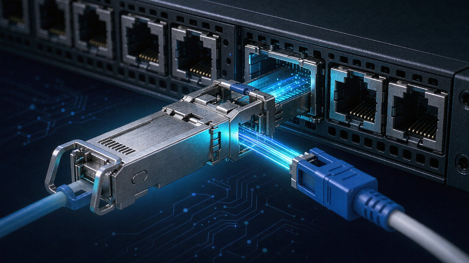
The short answer: an SFP module is a finger-sized optical transceiver that plugs into a matching cage on a switch, router, server NIC or media converter, and turns the host's high-speed electrical signal into light — then back into electricity at the far end. The name is an acronym for Small Form-factor Pluggable, and "pluggable" is the operative word: you can add, swap or upgrade a port without touching the chassis or powering anything down.
That is the practical answer to what is SFP: a standard, not a brand. Any vendor can build to it, which is why modules and cages from different suppliers mate with each other.
The definition itself is easy. What buyers actually need is the layer underneath it: which cage the module fits, which line rate the host will accept, which reach class matches the fiber already in the ground, and which firmware detail decides whether the port comes up at all. This guide works through those layers in the order a project hits them.
What is SFP, and what is happening inside the shell
An SFP is a standardized package before it is a product. The mechanical and electrical ground rules come from the SFP MSA (originally published as INF-8074), which fixes the shell dimensions, the 20-pin edge connector, the 3.3 V supply and the two-wire management bus. Because every vendor builds to the same drawing, a module from one supplier physically fits a cage from another — that interoperability is the entire point of the multi-source agreement.
Inside the metal housing, a 1G SFP module is a small optical engine with four functional blocks:
- Transmit side. A laser diode — Fabry-Perot for short 850 nm multimode links, DFB for 1310 nm and 1550 nm single-mode work — driven by a laser driver that shapes the modulation current. The laser, its monitor photodiode and the coupling optics are usually packaged together as a TOSA.
- Receive side. A photodiode (PIN for most reaches, avalanche photodiode for long-haul parts) plus a transimpedance and limiting amplifier that restores a clean logic signal. This subassembly is the ROSA.
- Control and memory. A microcontroller that reads the internal sensors and serves the management interface, backed by an EEPROM holding two memory pages.
- The management map itself. Page A0h carries identity — vendor name, part number, serial number, date code, supported link lengths and the transceiver code that tells the host what kind of module it is. Page A2h carries live diagnostics, which is where troubleshooting usually begins.
That second page is defined by SFF-8472 and is the reason a modern network OS can print real numbers instead of guessing. It exposes live values for case temperature, supply voltage, bias current on the laser, and optical power on both the transmit and receive side, each with warning and alarm thresholds written at manufacture. SFF-8472 also specifies whether those values are internally calibrated and reported in engineering units, or externally calibrated and reported as raw counts that the host must convert; it likewise distinguishes average received power from optical modulation amplitude. When two vendors' modules report slightly different Rx readings on the same link, the calibration bit is often the explanation.
Our 155M, 1.25G and 2.5G SFP family follows this same map, which means the diagnostic commands your operations team already uses — reading Rx power, comparing it against the link budget — work without any vendor-specific tooling. Full part numbers and per-part Tx/Rx windows are on the SFP product page.
What is an SFP port, and how do you identify one
The shortest answer to what is an SFP port is: the cage. It is the receptacle that accepts the module — a rectangular metal opening with a spring-loaded latch tab, a guide rail for the 20-pin connector at the back, and an EMI gasket around the mouth. Populating it takes one motion: slide the module in until the latch clicks. Removing it takes one small lever.
Three practical points follow from that design, and each one causes field mistakes:
The cage does not set the speed; the host SerDes does. An SFP+ cage and an SFP cage are dimensionally the same opening. What changes is the electrical grade behind it — impedance continuity, crosstalk control between the transmit and receive pairs, and thermal path. That is why a 25G-capable cage can host a 1G module and run it at 1G, while a 1G-only cage cannot be pushed to 10G or 25G no matter what you insert. Buying the higher-grade cage footprint costs little at design time and buys years of headroom.
Optical ports and copper ports look different, and that difference matters. An SFP port takes a module; the module then presents either an LC duplex (or SC, or simplex for BiDi) optical connector, or an RJ45 jack in the case of a 1000BASE-T copper SFP. If your switch has a row of RJ45 jacks, those are copper ports, not SFP ports — even when the same switch also offers SFP slots alongside them.
Wider families use a wider connector. QSFP+, QSFP28, QSFP-DD and OSFP modules have four or eight electrical lanes and a 38-pin (or double-row) interface, so they will not enter an SFP cage at all. Mixing them up in a bill of materials is a costly error; the physical difference is obvious once you have held both.
Speeds, reaches and deployment tiers: matching the module to the link
Three decisions cascade in a fixed order — rate, then reach, then deployment tier. Take them out of order and you end up with a technically compliant bill of materials that will not light up.
The SFP family at a glance: one shell, three speeds
The confusing part of the naming is that SFP, SFP+ and SFP28 describe the same mechanical envelope carrying three electrical generations. The table below is the one to keep open while reading a switch datasheet.
| Variant | Lane rate and encoding | Electrical / management spec | Lanes | Host port it fits | Typical reach envelope |
|---|---|---|---|---|---|
| SFP (1G) | 1.25 Gb/s, 8b/10b | INF-8074 SFP MSA, SFF-8472 DDM | 1 | 1G SFP cage, or any faster SFP-family cage | 550 m to 120 km |
| SFP+ (10G) | 10.3125 Gb/s, 64b/66b | SFF-8431 (SFI), SFF-8432 mechanical | 1 | SFP+ cage, or SFP28 cage | 300 m to 80 km |
| SFP28 (25G) | 25.78 Gb/s, 64b/66b | IEEE 802.3by, SFF-8402 | 1 | SFP28 cage | 100 m to 40 km |
| QSFP+ (40G) | 4 × 10.3125 Gb/s | IEEE 802.3ba, SFF-8636 management | 4 | QSFP+ cage (38-pin) | 100 m to 10 km |
| QSFP28 (100G) | 4 × 25.78 Gb/s | IEEE 802.3bm, SFF-8636 management | 4 | QSFP28 cage (38-pin) | 100 m to 10 km+ |
Two engineering decisions explain the differences. First, the 1G generation used 8b/10b line coding, so a 1 Gb/s payload needed a 1.25 Gbaud line rate and the clock recovery circuitry lived inside the module. The 10G generation changed where that work happens: serialization and clock-data recovery moved to the host across the SFI interface that SFF-8431 defines, and 64b/66b replaced the older coding. Less circuitry in the module means less heat per port, which is what let SFP+ displace the bulky XENPAK and X2 hardware. Second, 25G keeps the single-lane architecture but raises the signalling rate again, which is why SFP28 cages need better thermal paths — the cage is the first link in the cooling chain, and at 25G that stops being a formality.
Reach classes: how distance chooses the part number
Once the rate is settled, distance and fiber decide everything else. Wavelength is not a preference; it is a consequence of the fiber you already own. Multimode glass only supports the short-wave classes, while single-mode opens the whole ladder up to 120 km.
| Application class | Wavelength | Fiber | Reach | Representative part (Canjin) |
|---|---|---|---|---|
| 1000BASE-SX | 850 nm | OM2/OM3/OM4 multimode | 550 m | BLP11C-33BL |
| 1000BASE-LX class | 1310 nm | 9/125 µm single-mode | 20 km | BLP335-33BL |
| Extended 1310 nm | 1310 nm | Single-mode | 40 km | BLP336-33BL |
| 1550 nm long reach | 1550 nm | Single-mode | 40 km | BLP556-33BL |
| 1000BASE-ZX class | 1550 nm | Single-mode | 80 km | BLP558-33BL |
| BiDi, one fiber strand | 1310/1550 nm | Single-mode, simplex | 20–120 km | BLB355-33BL to BLB459-33BL |
| CWDM, muxed lambdas | 1270–1610 nm | Single-mode | 40–120 km | BLCXX6-33BL, BLCXX9-33BL |
The long-reach rows are where projects fail quietly. A 120 km BiDi part such as BLB459-33BL is not a licence to build a 120 km span without arithmetic: usable distance is transmit power minus receiver sensitivity minus every connector, splice and patch-panel loss in the path. Our specification tables publish Tx minimum, Tx maximum and Rx sensitivity per part number precisely so that calculation can be done before the order, not after the link refuses to come up. Attenuators are also a real requirement on short spans that use long-reach optics — an 80 km module on a 2 km run can overload the receiver just as surely as a weak signal can starve it.
Fiber selection gets its own treatment in our note on single-mode versus multimode fiber, but the rule of thumb is simple: measure the actual cable route, add margin for routing and patch panels, then choose one class above the result.
Where these modules sit in a live network
The 1G SFP never became obsolete; it moved down the hierarchy. You will still find it on subscriber-facing OLT uplinks and ONU links in FTTx builds, on campus aggregation and access switches, on industrial and utility networks where a 155M or 2.5G rate matches the legacy protocol, and on management and out-of-band paths where a 10G port would be wasted money and wasted heat.
SFP+ occupies the enterprise core and the 10G server uplink tier that most organizations built between 2015 and 2022. SFP28 took over the server-facing role in cloud and AI fabrics because four 25G lanes aggregate cleanly into a single 100G QSFP28 port — the breakout pattern that leaf-spine designs are built around.
The volumes behind that shift are no longer marginal. Industry estimates for 2026 put 800G-and-above modules at well over half of total transceiver shipments, with 800G units alone in the tens of millions and 1.6T reaching its first year of commercial volume. That headline growth sits above the SFP layer, but it pulls the whole hierarchy with it: every new AI rack needs leaf ports, management ports, console paths and storage links, and a large share of those are still single-lane SFP-family parts. Our SFP28 line covers the 25G tier at 100 m, 10 km and 40 km, and the SFP+ line covers 10G from 300 m to 80 km including BiDi and CWDM/DWDM variants.
Six checks before you place the order
- Rate and port capability. Confirm the host port's maximum rate and whether the line card actually lists the reach class you want. Some older 10G cards do not support ZR-class optics at all.
- Fiber type and measured distance. Multimode caps you at the short-wave classes; single-mode unlocks the rest. Use route length, not building dimensions.
- Link budget. Add up span loss and compare it against the module's Tx/Rx window. For anything beyond 40 km, do this on paper.
- EEPROM coding. Many platforms will only enable a port after reading a recognized vendor string. Ask for the coding to match the exact switch model and firmware release, and re-check after any OS upgrade — this is the single most common cause of "the module is dead" tickets. More detail in our EEPROM coding article.
- Diagnostics and temperature. Confirm DDM is implemented and that the operating case temperature range matches the enclosure. A 0–70 ℃ commercial part in an outdoor cabinet is a warranty claim waiting to happen; industrial variants exist for a reason.
- Power and mechanical fit. Check module power dissipation against the cage's thermal design, and confirm the connector type and latch style suit the patch panel density you are installing into.
FAQ
Can I put a 1G SFP module in a 10G SFP+ port?
Usually yes. Most SFP+ and SFP28 ports negotiate down and will run a 1G module at 1G, provided the port configuration allows it. The reverse never works: a 1G-only cage has a SerDes fixed at 1.25 Gbaud and cannot carry a 10G signal.
Are SFP, SFP+ and SFP28 modules physically interchangeable?
They share the same shell and 20-pin connector, so they fit the same opening. They are not interchangeable electrically. The host port must support the module's rate, and the cage must be rated for the signal integrity and heat that rate produces.
What is the difference between an SFP port and an RJ45 port?
An SFP port is a cage that accepts a pluggable module and therefore supports fiber (or copper through a 1000BASE-T SFP). An RJ45 port has the jack built into the chassis and is limited to twisted-pair copper at the speed the PHY supports.
Why does a new module show up as "unsupported" in the switch?
Almost always a coding mismatch rather than a hardware fault. The switch read page A0h, did not recognize the vendor or part identifier, and disabled the port. Confirm the requested coding profile against the switch platform and firmware before assuming the module failed.
How do I tell whether a link problem is the module or the fiber?
Read the diagnostics first. Zero received power with normal bias current points to a broken or disconnected path. Low but non-zero receive power points to loss — dirty connectors, tight bends, too many splices. Received power above the receiver's maximum points to over-driving, which calls for an attenuator. Bias current drifting upward with falling output power is the signature of an ageing laser.
Does a longer-reach module always give a better link?
No. Reach class is a budget, not a guarantee. Long-reach parts have higher launch power and tighter receiver specs, and on short spans they can saturate the receiver. Match the class to the measured distance, then verify the budget.
Standards and references
- SFF-8472 — EEPROM map and digital diagnostics for SFP/SFP+ modules.
- SFF-8431 — SFP+ electrical and mechanical specification.
- SFF-8402 — SFP28 (25G) mechanical and electrical specification.
- IEEE 802.3 — the base Ethernet standard that defines 1000BASE-X, 10GBASE-X and the SFP family's rate tiers.
- MSA documents (SFP, SFP+, SFP28) — multi-source agreements behind interchangeable pluggables.
Send Us Your BOM — We Will Quote the Rest
Share your model list, target speeds or link distances. Our engineers respond with matched part numbers, lead time and pricing.


